

Thermoforming Part Design and Development
Partner with Shirley K’s to design and develop a thermoformed part engineered for manufacturability from day one.
Developing a new thermoformed plastic part involves more than just forming. Shirley K’s supports the development process — from initial design review through tooling and first-article approval.
Start a Development Project | Call: (740) 868-8140
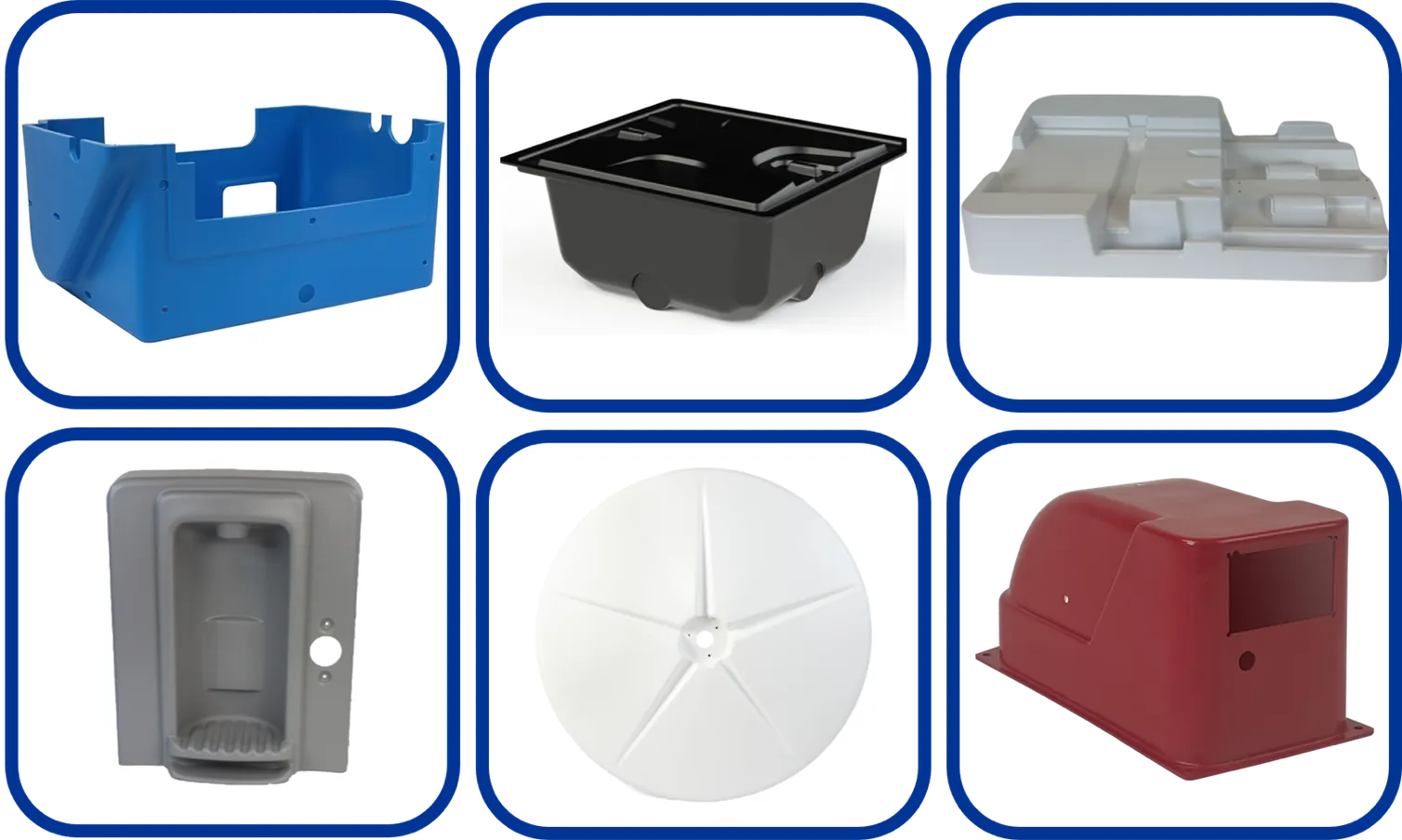
Examples of parts we’ve formed
WHAT WE SUPPORT
- Design review for thermoformability — draft angles, wall thickness, radii
- Tooling design and fabrication for your new part
- Material selection guidance — contact us for available options
- First-article production and approval process
- Production ramp to short-run quantities (dozens to hundreds per order)
- Production ramp to large-run quantities (thousands per order)
- In-house CNC trimming for precision finished parts
WHAT TO BRING TO A DEVELOPMENT DISCUSSION
- Part concept (sketch, reference part, verbal description)
- Material requirements (if known)
- Target quantity per order and target quantity per year
- Key dimensional or performance requirements
RELATED
- What to Send for a Quote
- Custom Thermoforming Overview
- Low Volume Thermoforming
- Custom Vacuum Forming Services
Start Your Development Project
Common Questions About Thermoformed Part Design
What makes a part well suited to thermoforming?
Thermoforming favors parts with generous draft angles, radiused corners rather than sharp internal edges, and geometry that can be drawn from a single mold face. Large surface area, shallow to moderate draw depth, and tolerance for some wall-thickness variation all work in the process’s favor.
How does draft angle affect a thermoformed part?
Draft is the taper applied to vertical walls so the finished part releases from the mold. Insufficient draft makes parts difficult to eject and can scuff or distort walls. Deeper draws generally require more draft, and male and female tooling have different draft needs.
Why does wall thickness vary in a thermoformed part?
The sheet starts at a uniform thickness and then stretches as it is drawn into the mold. Material that travels farthest thins the most, which is why deep corners are typically the thinnest section of a formed part. Designing with this in mind is central to thermoform part design.
What is the difference between a prototype tool and a production tool?
Prototype tooling is built to validate form, fit, and function at low cost and short lead time, and is generally not intended for sustained output. Production tooling is built for durability and cycle time over a long program life, and costs more to produce as a result.
What file formats are used for thermoforming part design?
Solid model formats such as STEP and IGES are commonly exchanged for tooling work, while STL is frequently used for additive processes and 2D drawings communicate tolerances and critical dimensions. Confirming accepted formats with a supplier before sending files avoids translation problems.